Distributed ray tracing does not mean ray tracing on a distributed system. The term here means distributing the rays by an analytic function, say a cone. The original paper for this can be found here.
The goals of the project were to simulate:
- Gloss and transparency
- Penumbra shadows
- Depth of field
- Motion Blur
Gloss and Translucency
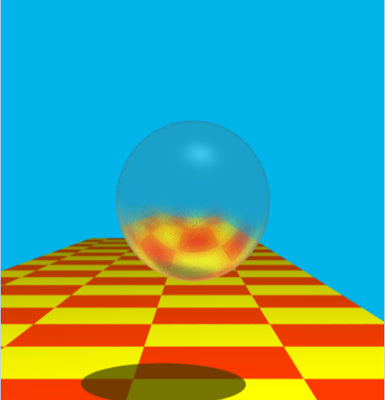
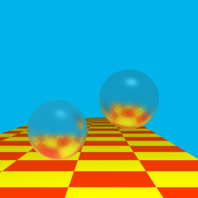
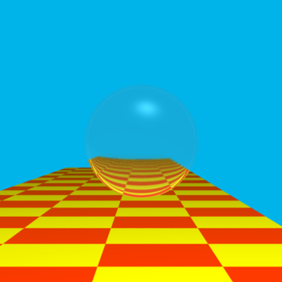
At each point of intersection when a reflected/refracted ray is calculated, I create a cone of rays and send them out to find the shade of the point of intersection. Creating a cone is reduced to creating a circle who’s center is somewhere (a point at a distance T from the intersection point) on the reflected/refracted ray. The circle is found by creating radius vectors which is pretty much an exercise on cross product of vectors. The results are given below.
Penumbra Shadows
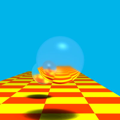
Raytracing gets sharp shadows because the light is modelled as a point light. To get penumbra shadows the light itself needs to be modelled as an area light. This is easy to do, all that is required is to model the light as a circular area with the original point as the center and find points on the circle. Then, for each point send shadow rays to all those points and see which of them are in shadow and which are not and calculate a fractional number. So if all the rays are in shadow then the number is zero and if none are in shadow then the number is 1. This number is simply multiplied to the shade of the point to get the shadow.
Depth of field
Since a typical raytracer uses a pin hole camera model, I thought that I could obtain depth of field(dof) by simply giving the lens an area. I was sadly mistaken as the image below shows.

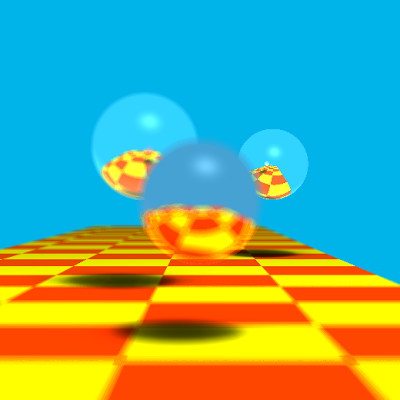
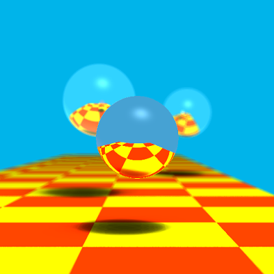
The result above is the same that occurs when the same film is exposed multiple times. My mistake was that I hadn’t allowed for a focal plane. The idea was to have a plane on the lens axis to which a test ray would be shot from the old pin hole model. The intersection of this ray with the focal plane would be noted and then multiple rays would be shot from the area lens to this point. So all objects near the focal plane would be in focus while those away from it would not. The three images given below show three different objects in focus.

Motion Blur
This is achieved by raytracing the image, then moving the sphere slightly, raytracing it again and averaging the colors so obtained with the previous ones.
This is the result that looks closest to what the paper shows. However it looks like a vibrating body and doesn’t say which direction the body is headed.

The sphere is made to slowdown to give the impression that it is heading to the right but the effect isn’t quite right.

The results are given weights based on when they appear and averaged. This is closest to what I had in mind.
