Who needs shadows anyway?
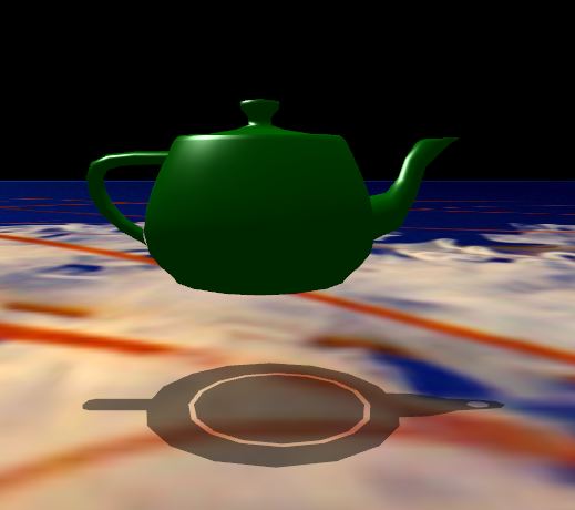
Shadows help in maintaining the illusion of reality. Take for example this image

The presence of the ominous shadow cues us as to the type and direction of light, and makes us think the teapot is resting on the table. It also helps set a mood.
Common Techniques (not necessarily real time)
- Shadow maps
- Shadow volumes
- Ray Tracing (here shadows are a side effect)
Shadow maps
This is an image based technique which makes it fast and ideal for static light and static objects. It is now directly supported by hardware and can be extended to approximate shadows from area lights and soft shadows.
Shadow volumes
This is a volumetric algorithm, which eliminates the problem of self shadowing. It was first popularized by Doom 3. They are more accurate than shadow maps but slower.
One of the key components needed for this algorithm is the depth buffer, which is 2D array of floating point numbers capped between 0 and 1.
The depth buffer has a one to one correspondence with the color buffer and stores the depth or Z value of each pixel that will be rendered. In it’s default setting it stores the Z value of the nearest object from the camera. This means that if we were to shoot a ray from the camera outwards and that ray intersects with more than one object then the smallest intercept would be stored in the depth buffer.
The two images below illustrate this idea.

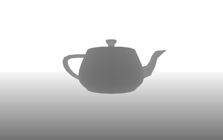
The first image is the scene and the second one shows what it’s depth buffer looks like, with white showing value of 0 and the greyscale illustrating the non zero values.
The other key component needed for this algorithm is the stencil buffer, which is similar to the depth buffer except it only contains signed integers. The stencil buffer is almost always used in conjunction with the depth buffer.
Here is how a typical stencil buffer operation would look like:
- If pixel passes the depth test (i.e. this pixel’s value gets written into the depth buffer) increment the corresponding pixel’s value in the stencil buffer)
- If pixel fails the depth test (i.e. this pixel’s value does not get written into the depth buffer) decrement the corresponding pixel’s value in the stencil buffer)
Finding the silhouette
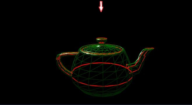
The first step for computing shadow volumes is to find the silhouette, which is the edge beyond which light does not fall on any triangle of the surface.
Here is an illustration, the arrow indicates the direction of light.
The algorithm for finding the silhouette is pretty simple, but time consuming:
- Initialize an empty contour map
- For each triangle of the surface
- If the angle of incidence between the surface normal of the triangle and the direction of light is not withing 0 and 90 degree, then this triangle is in shadow so
- For each edge of the triangle
- If this edge is already in the contour map remove it
- Otherwise add it
- For each edge of the triangle
- If the angle of incidence between the surface normal of the triangle and the direction of light is not withing 0 and 90 degree, then this triangle is in shadow so
If a triangle is in shadow then at least one of it’s three neighbouring triangles will also be in shadow and that’s why we need to remove the edge that is common to them both.
Once the silhouette is identified we need to extend it in the direction of light to create a new surface.
With the preliminaries behind us now for the full algorithm

This cycle needs four draw calls
- Draw the basic scene with only ambient light
- Draw the extruded surface culling back faces
- Draw the extruded surface culling front faces
- Draw the basic scene with diffuse light for only those pixels which pass the fragment test
Why does this work?
Let’s start with this image first
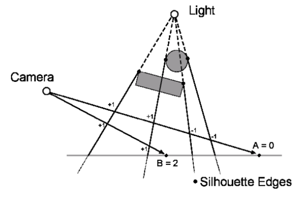
The two silhouette edges on the left were rendered during the second draw call with back faces culled, these silhouettes surfaces would be closest to the camera and would pass the depth test so the stencil would be incremented for both points A and B.
Similarly the two silhouette edges on the right were rendered during the third draw call with front faces culled, these silhouettes surfaces would be closest to the camera and would pass the depth test so the stencil would be decremented for point A but not for point B.
So when we get to the fourth draw call the stencil buffer for point B would be a non zero value but for point A the stencil buffer would hold 0. This means when we render the scene with diffuse light point A would get illuminated but not point B, thereby creating a shadow.
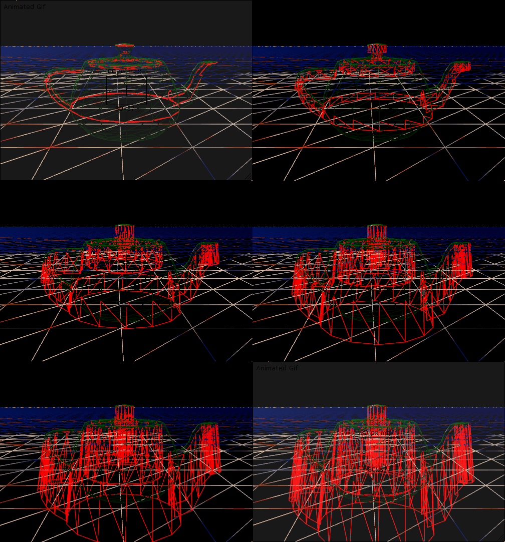
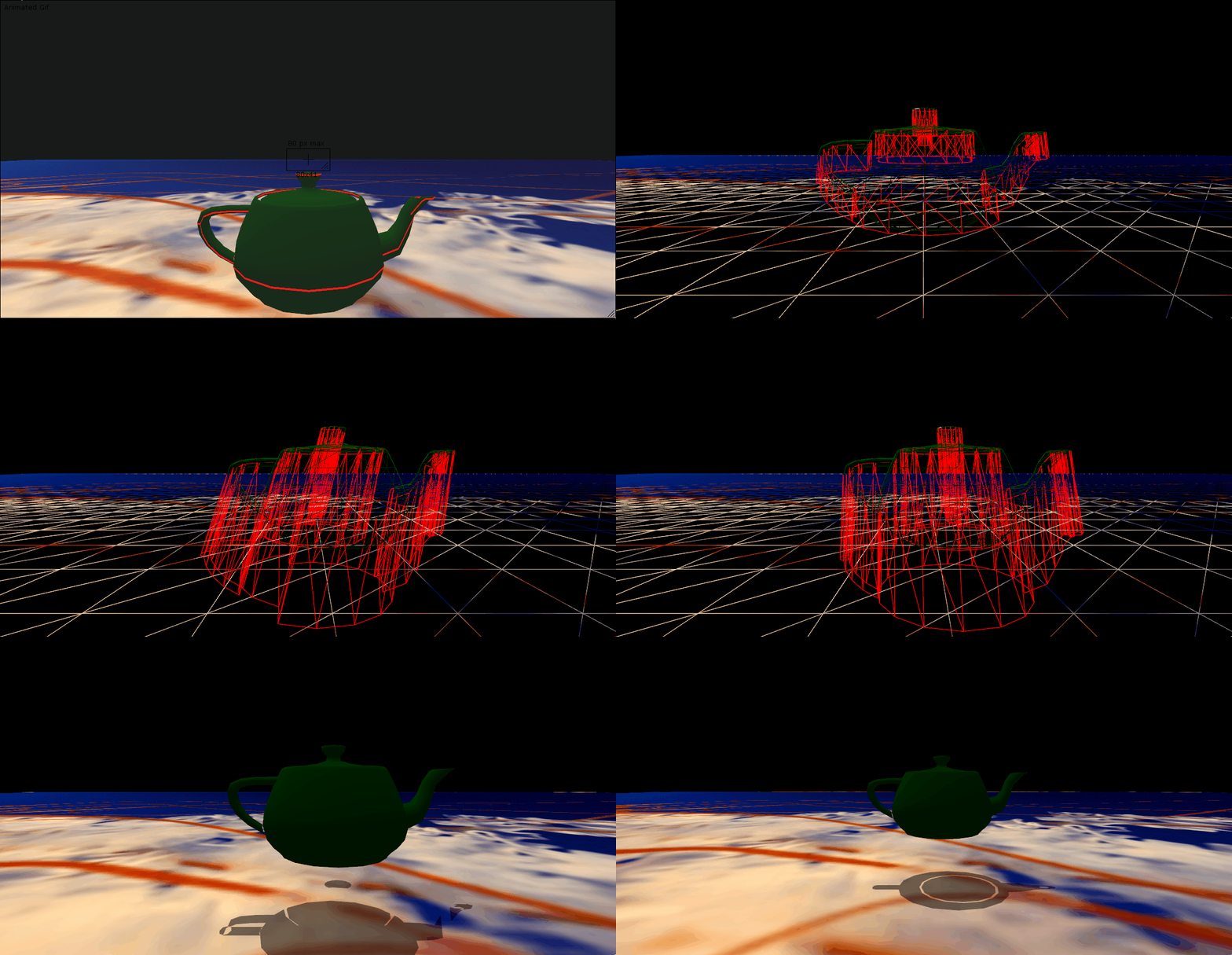
Here follows an animation of the process.
There are artifacts in the shadow, noticeably the circular rim coming from the lid of the teapot.
This is one of the drawbacks of this algorithm, the surface being rendered needs to be airtight. The lid and the nozzle both contain holes. When the silhouette is created, it works itself around these holes and extruding it creates a small area where the the points have value of zero in the stencil. Here’s is what the stencil buffer looked like. The grey areas show different non zero values while black means the stencil had zero for that pixel.
Room for improvement?
Hell yeah. The silhouette detection algorithm runs on the CPU, this kind of algorithm is ideal for the geometry shader, but that is a task for another day.
