
Raison d’etre
Although motion capture allows us to animate human motion, the data first needs to be processed before it can be applied to models. Hence if this data is used directly in real , the resulting animation will have artifacts. If there are multiple joints in a small area, such as in fingers the amount of noise in the data will be even higher.
The purpose of this project is to create an alternative technique by which finger movement while playing a musical instrument such as the piano can be animated in real by analyzing the music that is being played.
Solutions
There are two ways this problem can be tackled.
The first involves using a system such as Shape Hand which is shown in the figure below:

The shape-hand is a special motion capture glove designed specifically for capturing finger movement. Although such a device makes it easy to capture finger movement it makes holding and playing a musical instrument cumbersome. Also, each actor who plays an instrument in the script will have to be provided with a shape-hand system which will increase the cost of production.
The second option involves using the information in the music that is being played to estimate the finger motion and is the topic of this project.
Project goals
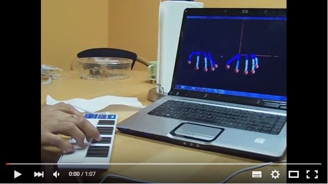
With the problem defined in the previous section, the goal of this project is to create a framework that takes in MIDI input signals through a USB keyboard controller and provides an animated view of the fingers that are likely to be used in playing the notes. Since the project will synthesize the data in real it will be possible to verify the accuracy of the process by looking at the finger movement of the person playing the piano and comparing it with the animated view that the project provides.
Project architecture
The following diagram shows the components of the system:

MIDI keyboard
A simple MIDI USB controllercan be used for this purpose.Several libraries exist which allow interfacing between the USB controllers and the OS. For the purpose of this project the RtMidi [7] library was chosen. It is written in C++ and follows an object oriented approach. It allows both MIDI input and output functionality through the use of two classes called RtMidiIn and RtMidiOut respectively. Only the former is used in this project. A MIDI signal is 3 bytes long. The first byte contains status information which includes:
- Note turned on/off data.
- The channel data.
The second two bytes contain the data of the signal which includes:
- The value of the note in the second byte
- The velocity with which the note was hit in the third byte.

For the purpose of this project the channel information is unnecessary since only one instrument is used. The velocity of the note is not used as the IK engine used does not allow speeding or slowing down motion.
MIDI Transcriber
The purpose of this module is to take MIDI signals as input and convert it into position data for the IK engine and forms the bulk of the work done in this project. It consists of two units. The first unit converts the MIDI signal into distance offsets on the keyboard. Figure below shows a note table that was used for this purpose.

The distances were measured on a standard CASIO keyboard taking the left end as the origin. This data is stored in a map. When the musical note information is obtained from the keyboard the corresponding distance is looked up from the map. On a piano the sharp notes denoted by the # symbol correspond to the black keys. The second unit takes the distance offset and decides, based on the current state of the ten fingers which finger is most suited to play the note and sends this information to the IK engine. Figure 2.4 shows a class diagram which provides a holistic view of the relations between the main classes.

The Connectorclass is the entry point which contains references to the MidiMain, BvhData and StartHand classes. These three classes inherit from the Poco Runnableclass. The Connectorclass starts these three classes and waits for them to join.
The BvhDataclass contains two lists of Nodeobjects (which is data required by the IK engine) for each hand. It is instantiated and passed into the StartHandclass so that when the two hands are created during the startup of the IKengine the Nodeobjects that get created can be added to the lists. From then on the BvhDataclass reads the angle values from the lists at 24 fps as the IK engine moves the hands. A client can be created that would send this string data to the VT server.
The StartHandclass exists so as to be able to tie the IK engine into the multithreaded structure of this project. It also passes the reference of the BvhData class to the IK engine so that when the IK engine creates the two hands it adds eachNodeobject into the list contained in the BvhDataclass. The StartHand class starts up the mainmethod in the Mainclass which is the starting point of the IK engine. This will be described in the next section.
The MidiMainclass encapsulates the RtMidi classes. Once it is instantiated it listens for incoming MIDI signals on the USB port. It contains a PianoDistanceclass which contains the note and distance information shown inthe note table in figure 2.3. The MidiMain class instantiates two objects of the FingerPositionclass (one for each hand) and passes them to the Arbitrer and ScriptParserclasses.
The purpose of the Arbitrerclass is to arbitrate which hand should be used to play the note. For this purpose it invokes methods in the FingerPositionclass. There are two objects instantiated of the FingerPositionclass, one for each hand. The class diagram in figure 2.5 shows its main variables and methods. For simplicity only the variables corresponding tothe index finger is shown in the figure.
There are two sets of Pointvariables that store the co-ordinates of the hand. One set, called the currIndex variables store the co-ordinates of the points where the hand actually is located and is rendered by the IK engine. The second set, called the pianoRestIndex variables store the coordinates of the hands as they would be poised on the center of the piano. It was decided to use two different sets of variables so as to facilitate the transformation of the coordinate space in which the IK engine works and the co-ordinate space in which the piano exists.
The calculation of which finger is nearest to the note is done on the pianoRestIndex variables and the result is applied to the currIndex variables.

The currIndex and the four other Pointvariables named currMiddle, currRing, currPinky and currThumb store the co-ordinate data of the end effectors of each finger in each hand. It is the actual co-ordinates that the IK engine uses to render the hands. It is by changing the x, y and z vales in these variables that the finger motion isattained. To obtain the effect of playing a key the z value of these points is decreased. This simulates the effect of pressing on a key. When the z value is restored to its previous value, it simulates the effect of lifting the finger off from the key. For the sharp notes, the y and z values are changed simultaneously. Currently the x values are not changed, but they can give a morerealistic effect of playing the piano.
The pianoRestIndex and the four other Pointvariables named pianoRestMiddle, pianoRestRing, pianoRestPinky and pianoRestThumbstore co-ordinates that correspond to the imaginary position of the two hands on the piano.
The Pointinformation stored in the pianoRestIndex variables are used to create the indexData variables which are objects of type FingerData. Each indexData object encapsulates the instantaneous information of each finger such as the name of the finger, whether it is on a note, the distance that it is currently at, the note it is on and the Pointposition. The indexData variables are stored in a list.
The Historyclass works as a memory for each hand. It stores the distance of the note that was last pressed by the finger and uses that to determine if the next note corresponds to an increase or a decrease and accordingly selects the finger.
As MIDI signals are read by MidiMain, the distance information is read from PianoDistanceand converted into a Point data which is sent to the Arbitrer class. This class invokes the findClosestFingermethod for the left and the right hand respectively. A FingerData object corresponding to the finger in each hand which is close enough to be able to play the note is returned. The Arbitrerthen invokes the activateClosestFingermethod on whichever hand is closest to the position of the note.
The findClosestFingermethod at its simplest structure takes the Pointdata which corresponds to the location of the key which is to be pressed and calculates the distance of each finger in the specified hand from that point. It then sorts thisdistance and returns the finger which is at the least distance from the point and is currently not being used to press a note. However the sorting is applied only if the Historyclass is unable to decide if the next note is a higher note than the previous or a lower note.
A cross over is necessary when the hand is progressively playing higher or lower notes. For example if the left hand keeps playing higher and higher notes it must then move from the left side of the keyboard to the right side. Once the hand reaches the thumb finger, to play the next higher note the middle finger must cross on top of the thumb and occupy the note.
Similarly a cross under occurs when the hand keeps playing lower and lower notes. Once the little finger of the hand reaches a note, to play the next lower note the thumb cross under the little finger.
Cross over and cross under styles are commonly seen in the C major scale. For the system to understand if this style is to be played the Historyobject of each hand must be able to decide if the new note is a higher note than the previousor a lower note. Once the Historyclass makes its decision, the findNextAdjacentFingerand findNextNonAdjacentFingermethods are invoked to ascertain which finger to use.
-
The structure described works provided the first finger that gets pressed when no fingers are on the piano can be determined with accuracy. But for practical purposes the first finger that is pressed is more a matter of personal preference and style and therefore impossible to judge. Certain heuristics can be applied such as:
- Giving the index or middle finger higher preference if no other finger in the hand is on a key or if a sharp note is pressed.
- Using the little finger if the note pressed is close to the left or right extreme of the keyboard.
- Ensuring that if the note is on the left side of the piano then the left hand is used to play it provided the left hand is free to play the note.
Despite these heuristics, if a note is located in the center ofthe piano, it becomes impossible to tell which finger to use first. For this purpose another experiment was conducted to test how well the system works if the note information and the fingers used to play it are known and provided to it as a script. This is similar to lip syncing for actors.
IK engine
For the purpose of this project, it was decided to use an existing IK engine rather than make a new one. After going through a few librariesit was decided to use the IK engine created by Samuel R. Buss and Jin-Su Kim for their paper on the technique of Selectively Damped Least Squares for IK. Since their IK engine was written in C++, it became the de facto language in which the project was written.
The following image shows the kind of tree structure that the engine solved initially.

The yellow lines represent the rotation axis about which rotation occurs in the joint. The red spheres represent the targets which the end effectors of the tree try to reach. This provided an extremely simple interface that could be manipulated to create the necessary movement in the fingers.
In order to create a chain which can mimic the functionalities and restraints of the hand the measurements required were obtained from the paper on the Handrix. The hand has three kinds of joints:
- Distal Interphalange joint (DIP)
- Proximal Interphalange joint (PIP)
- Metacarpophalangeal joint (MCP)

Rotation about the PIP and DIP joints occur in only one axis. The MCP can rotate about two mutually perpendicular axes but with restrictionsin the angles. Figure 2.8 below shows the position of the joints.
In Samuel Buss and Jin-Su Kim’s IK engine, they used the concept of Nodeobjects to create the chains. Each Nodeobject has a vector representing the length of the bone, the rotation axis about which it must rotate and the minimum and maximum angles ofrotation that it is allowed to rotate through. These nodes are ultimately added to a Tree object which gives rise to the IK chain which is then recursively solved.
For the purpose of this project the recursive nature of the tree was replaced by a list of Nodeobjects called the metaCarpalsList which denotes the metacarpal bones. Each hand is a Treeobject and has such a list. Each bone was given a string name such as ‘index’, ‘middle’ etc. Nodeswere created for each joint in each finger separately with specific distance vectors and rotation constraints. The root of each such chain was then added to the list under the appropriate name.
Figure below shows a class diagram of the classes showing only the parts that were modified for this project.

The Mainclass is a continuation of the class shown in brief in figure 2.4. It is started by the StartHandclass. It invokes the BuildLeftHandand BuildRightHandmethods which create the two Treeobjects for each hand.
When the IK engine traverses the tree, instead of doing a recursion like in the initial library, it first iterates over the list to get to each metacarpal bone and then recurses over the node chain in that bone.
For the MCP joints which have more than one axis of rotation an initial Nodeobject is added to the list with one of the axes and then to this Nodeanother Nodeis added with the exact same distance vector but different axes of rotations and corresponding restriction angles. The two images in figure 2.10 show the final result from two different perspectives with the yellow lines showing the rotation angles. The Treestarts as a simple Node chain as understood by the IK engine. The wrist (shown with a red circle) has two mutually perpendicular axes of rotation. While rendering the wrist the IK engine has to iterate through the metaCarpalsList, where each item is another chain leading to each finger.
For each finger a red sphere has been added. Once the system determines which finger to use to play the note then the UpdateLeftTargetsand UpdateRightTargetsin the Main class methods are invoked. These methods take the Pointposition of the end effectors of each finger as input which they use to relocate the red spheres. The IK engine then moves the finger so as to reach the position of the spheres.


Once the left hand was created, a mirror image of it was created to obtain the right hand.

Results
Conclusion
As was seen from the results of using the system, creating a perfect correspondence between the actual finger movement and the ones replicated becomes increasingly complex as the left hand moves over to the right side of the keyboard and vice versa.
There are essentially two parameters that can be used to evaluate the effectiveness of the project:
- Strongly defined parameters such as response and speed: This directly depends on the refresh rate of the IK engine and so theycan be sped up or slowed down as needed.
-
Weakly defined parameters such as accuracy: This is weakly defined because there can be several styles of playing the piano. What is significant in this part is that even though the system is unable to match the finger movement, yet, it produces results which are not physically impossible. For example if the middle finger of the left hand is currently on a note and the next note that is being played is a higher note, then, at that instant, there are three fingers that can be used to reproduce this correctly:
- The index finger on the left hand.
- The thumb on the left hand.
- Any finger on the right hand provided the right hand is free to move.
The pianist will, in most cases either choose option 1 or 2, but the system may choose any one of these options and it is not an incorrect move.
In the example given above a wrong move will beif the system uses the ring finger or the little finger of the left hand to reproduce the motion.